

Positioning the boiler
Unpack, move and set the UNI 60 in place — floor, levelling, clearances and the flue connection, before any pipework or wiring begins.
Set the boiler in its final position, level, on a non-combustible floor, with the clearances already marked out — everything after this step is much harder to correct. The UNI 60 weighs 1,224 lb and must stay upright the whole way in.
Qualified trades only
The boiler must be connected according to a project developed by a specialist in hydronic heating systems, with the requisite qualification and experience. Electrical work requires a qualified electrician.
Before you move it
Confirm the room is ready
Clearances marked, floor rated and level, ventilation openings clear, chimney installed or at least positioned. See Boiler room and clearances.
Complete the delivery inspection
Damage and missing items must be recorded before the delivery is accepted. See What's in the box.
Check the route
30 in wide, 36 in deep, 65 in tall, ±5 %. Doorways, corners, stair widths and floor protection along the whole route.
Setting the boiler
Keep it vertical
Transport and handling must keep the boiler in the vertical position only. Loading and securing must ensure complete safety against mechanical damage.
Position on a non-combustible floor
Set the boiler on its supports on a level, load-rated, non-combustible floor.
Level it, then check the rear incline
Level the body. The clearance drawing calls for a minimum incline of 3° at the back wall reference — this is the allowance for the flue connection run, not a tilt of the boiler itself.
Verify final clearances
With the boiler in place, re-measure: 24 in back and sides, 36 in front, 28 in overhead, 12 in to combustibles.
Fit the ash pan
The ash pan goes outside the unit, at the front of the ash door — not inside the boiler.
Identify the connections
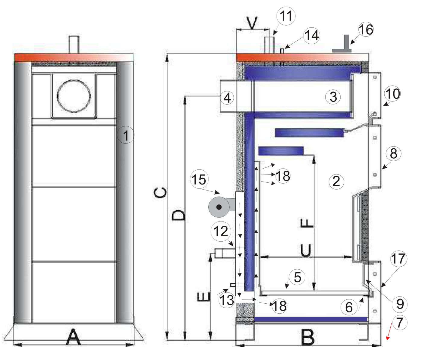
| Callout | Connection | UNI 60 size |
|---|---|---|
| 11 | Supply pipe | 2 in |
| 12 | Return pipe | 2 in |
| 13 | Drain pipe | — |
| 14 | Temperature sensor well | Boiler (CH) sensor + STB |
| 4 | Chimney connection | 8 in |
Connect the flue
Match the diameter
The chimney diameter must not be less than the diameter of the flue outlet — 8 in for the UNI 60.
Keep the run short and straight
Use as few bends as possible. Each one costs draft.
Respect the pipe clearance
12 in from the exhaust pipe to combustible material, or 6 in for double-wall stove exhaust pipe.
Seal and support
The connecting pipe must be supported independently of the boiler, and joints sealed. Acidic condensate attacks joints over time — see Chimney care.
Supply, return, relief valve, drain and return-temperature protection.
Fuel and storage
Which fuels the UNI 60 accepts, how dry wood must be, the calorific value of common species, and the 4 ft fuel storage clearance rule.
Hydronic piping
Pipe the UNI 60 — 2 in supply and return, mandatory safety relief valve, expansion tank, drain and return-temperature protection to stop condensation corrosion.