

Electrical and sensors
Wire the TIS Tronic 260U — 230 V supply, grounding, boiler sensor in the immersion well, STB safety thermostat on I1, and the optional PT1000 exhaust probe.
All electrical work on the UNI 60 must be done by a qualified electrician, and the boiler must be electrically grounded. The safety chain that protects the boiler from boiling is hardware, not software, so getting the STB right matters more than any controller setting.
Power off before any work
The device is under electric voltage. It is forbidden to work on connecting pumps, fans or other electrical devices while the regulator is connected to the power supply. Switch off the power and take measures against accidental switching on.
Before energising
Ground the boiler
Boilers TIS UNI must be electrically grounded.
Measure before you connect
Measure the ground resistance of the electric motors (pumps), and the insulation resistance of the electrical wires.
Fit a voltage stabiliser
For reliable and stable operation of the regulator, install a voltage stabiliser with an appropriate load rating.
Check the environment
The controller must not be exposed to liquids and must not be located in rooms with high humidity. Keep dirt and conductive dust out of it. Operating range: 5–40 °C, 30–75 % RH.
Terminal map
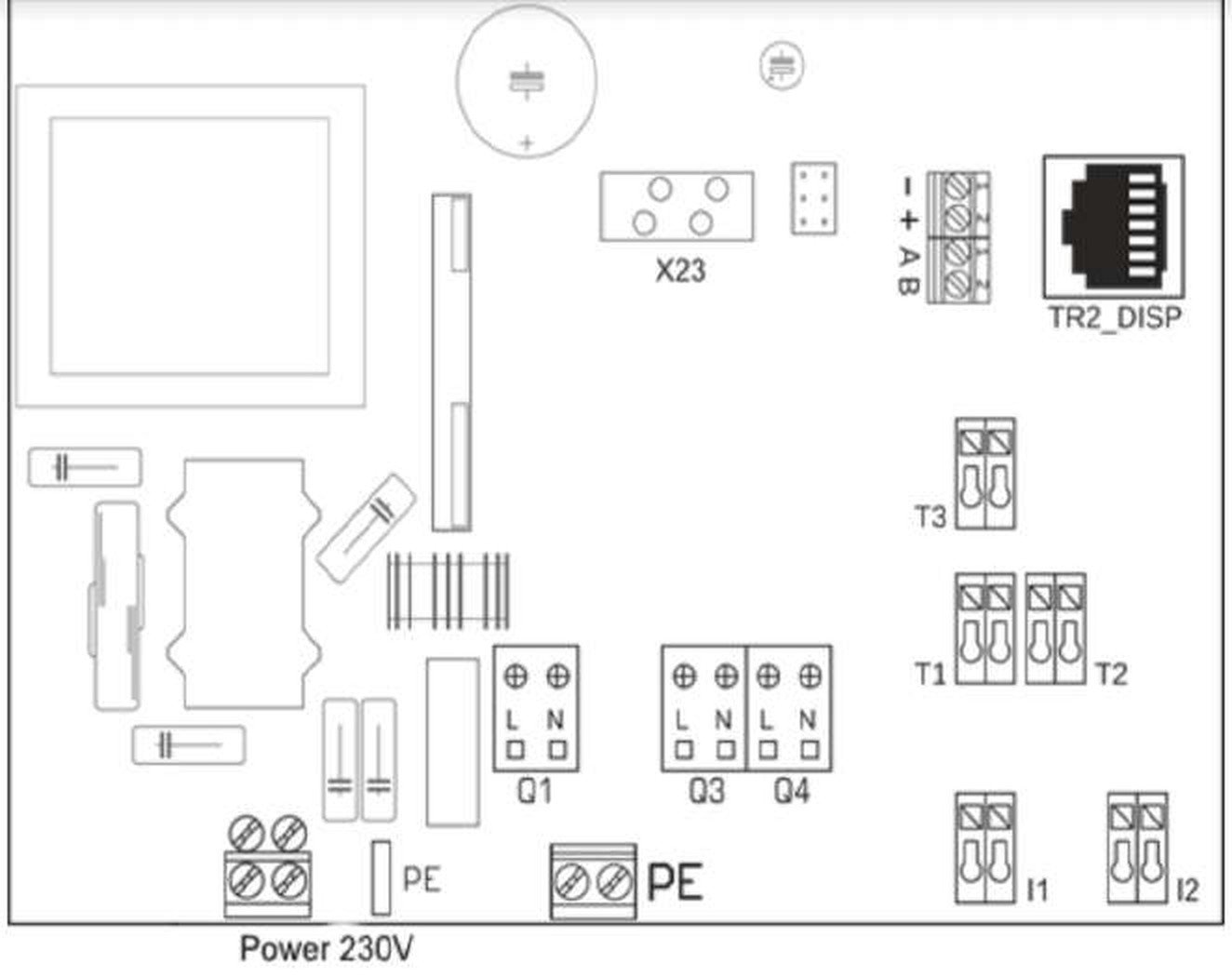
| Symbol | Designation |
|---|---|
Q1 | Fan outlet |
Q3 | Central heating pump outlet |
Q4 | Hot water (HUW) pump output |
I1 | Emergency thermostat STB |
I2 | Central heating room thermostat |
T1 | Boiler temperature sensor |
T2 | HUW temperature sensor |
T3 | Exhaust gas temperature sensor |
TR2_DISP | Panel connector |
X23 | Additional alarm (optional) |
- + A B | Alternative slot for additional modules |
Power comes in at 230 V on L and N, with PE earth terminals on the board.
Sensor placement
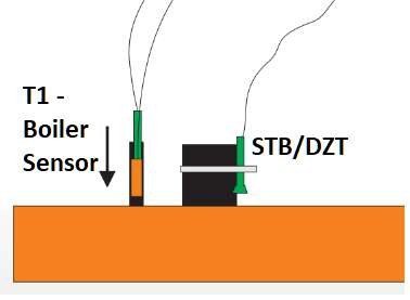
The CH sensor is lowered into the immersion well, followed by the thermal protection sensor (STB).
No liquid in the well
Adding any liquid to the immersion well is forbidden — no oil, no water, no paste. The sensor should be installed in a dry place.
If there is no immersion well, it is permitted to install the CH sensor on the supply branch pipe — up to the connection nut — and press it against the pipe with a metal clamp.
Sensor schedule
| Sensor | Terminal | Wire length | Type |
|---|---|---|---|
| CH sensor (boiler) | T1 | 0.8 m | KTY-81-210 |
| HUW (hot water tank) | T2 | 3 m | KTY-81-210 |
| Exhaust gases | T3 | — | PT1000 |
| STB | I1 | 1 m | Bimetal |
Sensors have no polarity — wiring sequence is not significant.
The exhaust sensor is not included
The PT1000 exhaust gas sensor is not supplied in the regulator standard kit. It is required for Brager Expert exhaust gases mode, which is the mode MBtek recommends for the UNI 60.
The STB safety chain
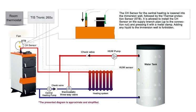
An independent bimetallic sensor turns off the fan if the water temperature in the boiler rises above 90 °C, preventing the water from boiling in the event of boiler overheating.
In accordance with PN-EN 303-5:2012, when the water temperature drops back to a safe value it is not possible for the fan to turn itself on again. The fan can only restart after:
- the water temperature in the boiler drops below 60 °C, and
- the error is manually reset on the control panel.
The protection sensor has two wires, connected to the I1 STB terminal. Polarity does not matter.
DZT thermal protection sensors
| Sensor | Opens at | Closes at |
|---|---|---|
| DZT-1 | 185 °F / 85 °C | 140 °F / 60 °C |
| DZT-2 | 200 °F / 95 °C | 155 °F / 70 °C |
Both connect to terminal I1. To operate at a higher temperature, order a DZT-2 from MBtek (Parts — UNI 15-40-60-95).
Replacing a sensor
Disconnect the power plug from the electrical outlet.
Unscrew the fixing screws on the back of the housing and remove the top cover.
Find the socket on the board using the terminal map above.
Press the connector with a flat screwdriver to release the fastening clip, then withdraw the wire.
Fit the new sensor. Correctly installed wires cannot be pulled out without pressing the terminal — if a wire slides free, it is not seated.
Connecting a 120 V circulator to the controller's 230 V outputs.
Frequently asked questions
Filling and water quality
Fill the UNI 60 with water below 2 ppm hardness, vent the system, and pressure-test to no more than 50 psi. Scale damage is not covered by warranty.
Wiring a 120 V pump
Connect a 120 V circulator to the TIS Tronic 260U using the supplied 220 VAC relay block — controller contacts 7 and 8, pump to 3 and 5 or 4 and 6.