

Wiring a 120 V pump
Connect a 120 V circulator to the TIS Tronic 260U using the supplied 220 VAC relay block — controller contacts 7 and 8, pump to 3 and 5 or 4 and 6.
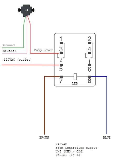
Connect the supplied 220 VAC relay block to the controller on contacts 7 and 8, then wire the 120 V pump through contacts 3 and 5, or 4 and 6. The controller's pump outputs switch 230 V; the relay block is what lets them control a North American circulator.
Wiring diagram
Procedure
Isolate
Disconnect the controller from the mains. Take measures against accidental switching on.
Wire the relay coil to the controller
Connect the 220 V relay block to the controller using contacts 7 and 8. This is the coil side — the controller's pump output switches it.
The coil leads in the diagram are the brown and blue wires marked 240 VAC from controller output.
Wire the pump through the relay contacts
Connect the 120 V pump to contacts 3 and 5, or 4 and 6.
In the diagram, the 120 VAC outlet feed lands on contact 5, and the pump power lead is taken from contact 3. Ground and neutral run directly from the outlet to the pump.
Verify before closing up
Check continuity and confirm no 230 V is present on the pump side. Only then restore power.
Which controller output?
On UNI units the relay coil is fed from the controller's pump output — Q3 for the central
heating pump, Q4 for the hot water pump. Each output is rated 1 A. Check your circulator's
inrush current against that limit.
Output ratings
| Output | Device | Rating |
|---|---|---|
Q1 | Fan | 1 A |
Q3 | Central heating pump | 1 A |
Q4 | Hot water (HUW) pump | 1 A |
The controller itself draws 4.5 W with no external devices connected.
When the pumps run
Pumps do not follow the fan — they follow temperature. Three settings govern them:
| Setting | MBtek value | Effect |
|---|---|---|
| Pump start temperature | 35 °C / 95 °F | All active pumps switch on above this boiler temperature. They switch off when it drops 5 °C below |
| Boiler cooling temperature | 78 °C / 172 °F | Above this, all circulation pumps in the heating system start, to shed heat |
| Maximum boiler temperature | 80 °C / 176 °F | External controls such as the room thermostat are ignored; fan control functions are disabled |
There are also two quenching-related pump settings — whether the central heating pump stops when the fire goes out, and how long after. See Quenching and fuel shortage.
NextRoom thermostatWiring a dry-contact or 24 VAC thermostat to terminal I2.
Frequently asked questions
Electrical and sensors
Wire the TIS Tronic 260U — 230 V supply, grounding, boiler sensor in the immersion well, STB safety thermostat on I1, and the optional PT1000 exhaust probe.
Room thermostat
Connect a room thermostat to terminal I2 on the TIS Tronic 260U — dry contact required, 24 VAC thermostats need an SPDT relay, and the contact logic must be inverted.