

Wiring reference
Complete TIS Tronic 260U terminal map, sensor schedule, output ratings and fuse specification, with the board diagram and hydraulic connection drawing.
Everything you need at the board, in one place. Disconnect the regulator plug from the 230 V supply before any repair work.
Board diagram
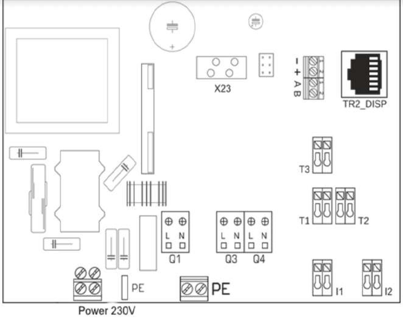
Terminal map
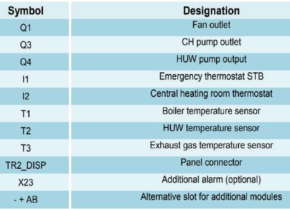
| Symbol | Designation | Type | Rating |
|---|---|---|---|
Q1 | Fan outlet | Output, 230 V | 1 A |
Q3 | Central heating pump outlet | Output, 230 V | 1 A |
Q4 | HUW pump output | Output, 230 V | 1 A |
I1 | Emergency thermostat STB | Input, dry contact | — |
I2 | Central heating room thermostat | Input, dry contact | — |
T1 | Boiler temperature sensor | Sensor | KTY-81-210 |
T2 | HUW temperature sensor | Sensor | KTY-81-210 |
T3 | Exhaust gas temperature sensor | Sensor | PT1000 |
TR2_DISP | Panel connector | Ribbon | — |
X23 | Additional alarm (optional) | Output header | — |
- + A B | Alternative slot for additional modules | Bus | — |
L N PE | Power 230 V and earth | Supply | 230 V / 50 Hz |
Sensor schedule
| Sensor | Terminal | Wire length | Type |
|---|---|---|---|
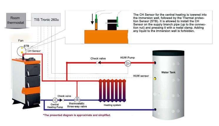
| CH sensor (boiler) | T1 | 0.8 m | KTY-81-210 |
| HUW | T2 | 3 m | KTY-81-210 |
| Exhaust gases | T3 | — | PT1000 |
| STB | I1 | 1 m | Bimetal |
Sensors have no polarity — the wiring sequence is not significant.
Exhaust sensor sold separately
The PT1000 exhaust gas sensor is not included in the regulator standard kit.
Hydraulic and STB connection
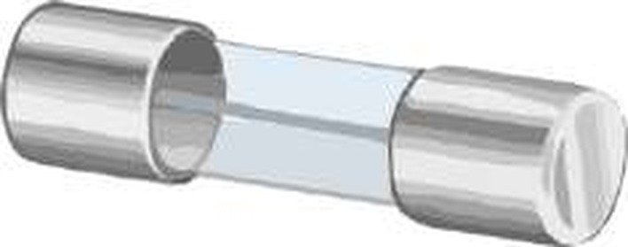
Fuse
| Property | Value |
|---|---|
| Voltage | 250 V |
| Current | 3.15 A |
| Diameter | 5 mm |
| Height | 20 mm |
Replace a blown fuse only with a new one of the same rating. Fuse failure is not covered by warranty.
Opening the housing
Unscrew the fixing screws on the back of the housing, then remove the top cover.
Isolate first
Before performing any repair work, be sure to disconnect the regulator plug from the 230 V power supply.
Seasonal electrical check
Before the heating season and during it, check:
- the technical condition of the wires;
- the fastening of the regulator;
- and clean it of dust and other contaminants.
Disposal
The crossed-out wheeled bin symbol means the product must not be disposed of in regular waste bins. Return used equipment to a designated collection point for waste electrical and electronic equipment. The manufacturer's environmental registration number is 000002627.
NextFirst firingThe controller is configured. Time to light it.
Alarms
Every TIS Tronic 260U alarm — sensor errors, HUW overheating, lack of fuel, failed fire-up, emergency temperature and STB overheating — with causes and how to clear them.
First firing
Light the UNI 60 for the first time — check the draft, set the controller, load the firebox, ignite, run Start Fire, and stay with the boiler.