

Hydronic system design
Design the UNI 60 hydronic system — closed loop, expansion tank, safety relief valve, return-temperature protection and the recommended MBtek installation scheme.
Design the UNI 60 into a closed system with an expansion tank, a safety relief valve, return-temperature protection and thermal storage. The boiler will physically run without most of those; it will not last without them.
Closed systems only, in practice
If the boiler is used on an open heating system the corrosion rate will be very fast and the warranty is avoided. The warranty period reflects that: 3 years on the boiler body for open systems versus 10 years for closed systems.
The recommended scheme
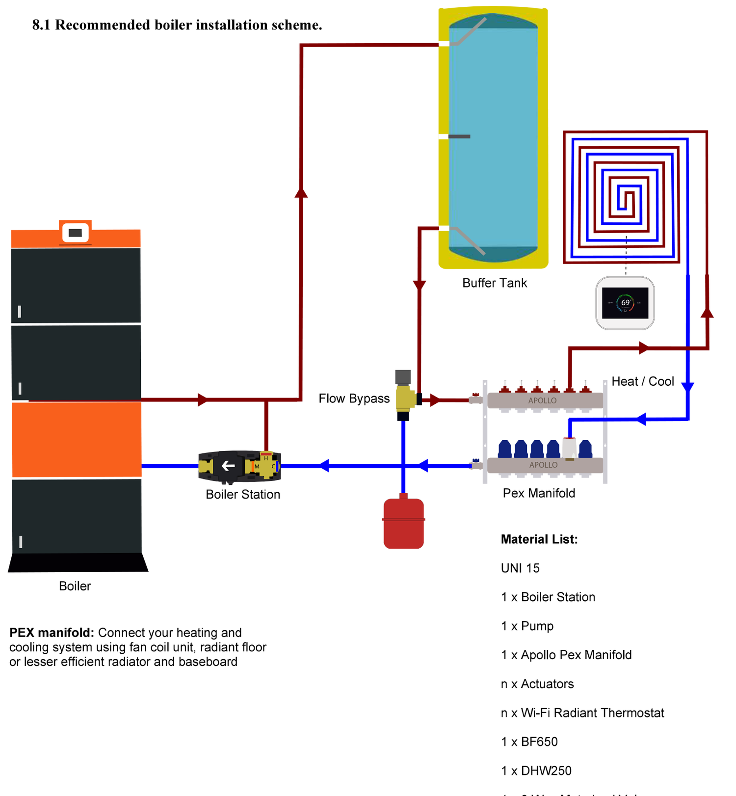
Material list for this scheme:
| Item | Qty |
|---|---|
| UNI boiler | 1 |
| Boiler station | 1 |
| Pump | 1 |
| Apollo PEX manifold | 1 |
| Actuators | n |
| Wi-Fi radiant thermostat | n |
| BF650 buffer tank | 1 |
| DHW250 domestic hot water tank | 1 |
| 3-way motorised valve | 1 |
The PEX manifold connects your heating and cooling system using a fan coil unit, radiant floor, or the less efficient radiator and baseboard options.
Mandatory components
Safety relief valve
Never use the appliance without a relief valve. Position the discharge drainage so that it is safe if the valve opens — it will discharge boiling water.
Expansion tank
On closed and open heating systems, boilers must be installed with an open or membrane expansion tank. The volume depends on the heating volume and is calculated in the design of the heating system.
Return-temperature protection
To avoid condensation, a thermostatic valve should hold the return above roughly 130 °F. Where direct circulation is used without a thermostatic valve and the return falls below 122 °F, the supply must be set to at least 149 °F.
Check valve on automatic make-up
If using automatic make-up water to the boiler, install a check valve according to local regulations. The system should be filled at a pressure not exceeding the maximum working boiler pressure.
Thermal storage
A full burn produces more heat than most buildings need at that moment. A buffer tank captures it, cuts cycling and improves comfort — see Buffer tank and hot water.
Pressure and temperature envelope
| Parameter | Limit |
|---|---|
| Maximum operating pressure | 15 psi |
| Never exceed | 36 psi |
| Maximum test pressure | 50 psi |
| Maximum water temperature | 185 °F / 85 °C |
| Recommended boiler setpoint | 149 °F / 65 °C |
| Minimum return temperature target | ~130 °F |
Natural circulation
If the system relies on natural circulation, install the boiler so the return water pipe sits below the radiator. Gravity systems need that height difference to move water at all.
Overheat behaviour
Design the system so heat has somewhere to go when the controller decides it must dump it. Two controller behaviours force circulation:
- Boiler cooling temperature (MBtek recommends 78 °C / 172 °F): above this, all circulation pumps in the heating system start.
- Maximum boiler temperature (recommend 80 °C / 176 °F): external controls such as the room thermostat are ignored, and fan control functions are disabled.
If every zone can be closed off by actuators at once, the pumps will have nowhere to push water. Fit a flow bypass — it is in the recommended scheme for exactly this reason.
Air and pressure in service
- Throughout the heating season, monitor the pressure in the system.
- Air must be removed during the first weeks of operation. Expect to vent repeatedly as dissolved air comes out of solution.
Sizing thermal storage, and how the controller makes domestic hot water.
Frequently asked questions
Chimney requirements
Specify the UNI 60 flue — 8 in minimum diameter, acid-resistant 316 stainless steel, insulated where exposed, to EN 1856-1 and EN 1856-2.
Buffer tank and hot water
Why a UNI 60 needs thermal storage, how the buffer tank fits the scheme, and how the TIS Tronic 260U prepares domestic hot water in Summer and Winter modes.